NEWS
Product knowledge
Application method of PLC Siemens in control system of rubber dam
Date:2011-10-24 Num:645
The Taoyuan River Rubber Dam is located in the territory of Shandong city of Linyi province. Rubber dam is made of high molecular composite material, which is formed by the size of the required size and the anchor in the bottom plate to form a closed, water (gas) filling and expanding. Without water, emptying the dam bag in the water (gas), the cross section can restore the original canal. Rubber dam can be used for flood control, irrigation, power generation, water supply, shipping, tide and urban landscaping, also can be used for the activities of cofferdam, canal system temporary water retaining works, etc..
2 The overall structure of the 2 system
The structure design of rubber dam control system as shown in Figure 1, mainly by the local measurement and control system and the remote monitoring system consists of two parts: supervisory control and data acquisition system (SCADA system). Rubber dam field control system uses SIEMENS S7-300 and S7-200 series PLC platform, using PLC as the core, the signal collected by various sensors, complete the downstream water level and the chamber water level, water level monitoring, ship detection Gegou, the opening height of the dam bag inner pressure, dam height and other parameters of the dam. It mainly includes two sets of S7-200 lock control cabinet, a set of S7-300 charge pump control cabinet, a water level monitoring station Gegou cabinets, traffic lights, electric butterfly valve and on-site installation of the data acquisition and related control equipment of the hardware system, at the same time, also including the use of the dam safety monitoring equipment osmometer.
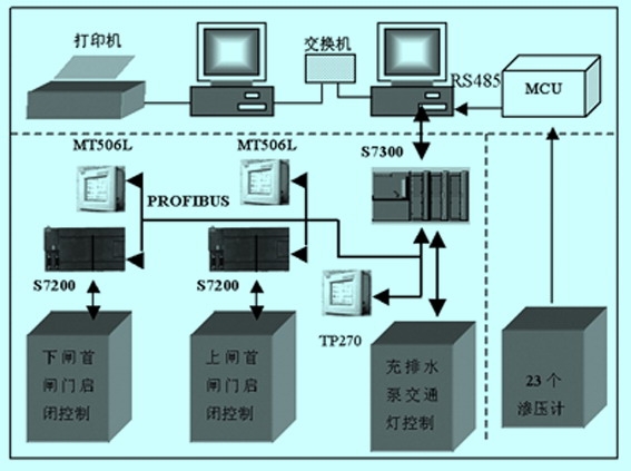
Figure 1 Rubber dam control system structure
PC remote control system is mainly composed of two industrial control computer and its monitoring software, dam safety monitoring equipment MCU, industrial switches and so on. Two industrial control computer, as a server, the other as a client, the client and server using OPC communication; monitoring software is the main control parameters setting, working condition display, operation control, statistical data and historical records query functions, data real-time receiving local sensor operation, record each dam the bag and the operation of the gate, the overall operation of a comprehensive monitoring of rubber dam control system.
In terms of communication, the two sets of S7-200 field lock control cabinet and S7-300 control cabinet using profi-busu agreement, Ge ditch water level S7-200 monitoring cabinet and S7-300 control cabinet using wireless radio remote transmission mode. The server and client are using industrial Ethernet communication. At the same time, the dam safety monitoring equipment MCU and monitoring host using RS485 protocol.
The rubber dam control system must be fully considering the safety and reliability of lock hoist and charge pump operation under the use of industrial control technology, sensor technology, data transmission technology and computer technology is mature, implementation of rubber dam shiplock and pump information real-time collection, automatic gate opening and closing, and the related environment accurately the monitoring and management of lock.
3 monitoring system design
3.1 gate and pump control
(1) local control: operators can switch to achieve the conversion through a set of manual control mode and automatic control mode. Under the manual control mode, the operator can open and close the gate or the pump according to the original way, and the action related information will be accepted by the superior department. Remote control can be performed in an automatic mode. Manual and automatic control mode can also be switched by remote monitoring system.
(2) remote control: according to different users through the network to the field control unit (PLC) of the instruction, the gate can be opened or closed automatically, water filling and drainage pump automatic start or stop the action by all levels of users according to access control.
(3) gate and pump start alarm: the gate will be opening and closing and opening and closing process, the gate hoist should be near the corresponding sound and light alarm device, to remind the attention of the staff at the scene.
(4) limit protection: at the top of the gate opening and closing device and the limit switch should be installed below the hoist operation range, once the closing device runs to the two position, the two limit switch will immediately notify the control unit, cut off the hoist power, in order to avoid. Beyond the scope of operation of closing machine.
(5) phase protection: in the opening and closing the power supply line inside the machine should be connected with the phase protector, avoid the hoist motor not normal operation of three-phase power phase sequence confusion caused by the.
(6) overload protection control circuit inside each hoist must be equipped with thermal overload relay, according to the different requirements of the motor power have different settings, when the motor overload occurs or other fault, the relay will automatically cut off the power supply of the motor, so as to avoid burning motor.
3.2 monitoring data
The real-time monitoring data should include: gate level, gate level, gate opening, gate gate, load up or down state, gate switch contactor, hoist protection device, state power and control power state, the operation button or switch state, gate hoist power supply voltage and current.
(1) water level monitoring: to install water level sensor according to the requirements of water level observation before and after the chamber and the chamber, so that the real-time water level before and after the real-time monitoring of the chamber and the chamber of information.
(2) automatic tracking and measuring a sluice gate action: whether or not, installed on the gate hoist transmission device on the gate level gauge should be real-time detection of gate height value, and upload to the site control unit.
(3) current and voltage monitoring: multi-function meter and configuration in the power supply line, used for real-time monitoring of current and voltage of the three-phase power supply, to hoist and provide reference data for close operation.
(4) hydraulic system: including hydraulic pressure monitoring, alarm signal (overvoltage, undervoltage), oil filter blocking alarm signal, low oil level alarm signal;
(5) environmental monitoring: equipped with temperature and humidity sensors in the generator room, the working conditions of real-time monitoring in the equipment room.
(6) monitoring: including lock signal state, on the downstream state, locking the gate up or down state, gate switch contactor, hoist protection device, state power and control power state, the operation button or switch state.
3.3 drainage control system
The dam filling and drainage control system is mainly composed of upper control system, charge pump, soft starter, electric control device, water level detection equipment, the dam height and the dam bag pressure detection equipment, according to the dam height, pressure and water level in the dam bag, filling and drainage of the dam bag through the water pump motor start and stop electric butterfly valve control and water pipe on the switch of the automatic control, the time required for the dam filling and drainage bag must fit in with the needs of Engineering application.
The dam filling and drainage control system mainly includes two kinds of flood season and the non flood season drainage control mode, the flood season, according to our Gegou level, make a closed-loop control, to adjust the height of the dam; the non flood season, according to the upstream water level, make a closed loop control to adjust the corresponding the height of the dam bag.
4 hardware system design
4.1 type programmable controller
According to user requirements, requirements of equipment parameters of PLC modular, high performance, high reliability, high speed instruction processing, user friendly, simple maintenance and service and reasonable price, considering the various PLC brand performance and cost, we choose the Simens programmable controller S7-200 and S7-300 series, S7-200 as a child as the master station, s7-300. Among them, the gegouba water level station PLC adopts cpu222 lock hoist control PLC using cpu226, S7-300 by cpu315-2dp.
4.2 extended from the station module
Extended from the station module (em277profib-us-dp): S7-200 can be CPU connected to the PROFIBUS-DP network. EM277 through the serial i/o bus to connect to the S7-200 cpu. Pro-fibus network through the DP communication port, connect to the EM277 PROFIBUS-DP module. This port can run any PROFIBUS baud rate between 9600 Potter and 12m Potter. As dp from the station, the EM277 module receives a variety of different i/o configurations from the main station, sending and receiving different amounts of data to the master station. This feature allows the user to modify the amount of data transmitted to meet the needs of the practical application. Different from many DP stations, the EM277 module is more than just a i/o data transmission. EM277 can read and write variables defined in the s7-200cpu data block. In this way, the user can exchange any type of data with the master station. We will move the data to a variable in the CPU memory S7-200, can be input, count, timer value or other values sent to the master station. Similarly, data from the master station is stored in the variable memory in the s7-200cpu and can be moved to other data areas. EM277 PROFIBUS-DP module DP port can be connected to a DP station on the network, but still can be used as a MPI from the station with the same network such as SIMATIC or s7-300/s7-400 programmer CPU and other communication station.
5 system software design
5.1 operating system software
Rubber dam monitoring system operating system software using Windows Server 2000. It is based on Windows NT server 4 on the further development of active directory, it uses the way of data storage is similar to the exchange server, called extensible storage service, its characteristic is not need to define the database parameters, can achieve dynamic growth, excellent performance. Index, which can be easily and quickly searched and positioned, is built on top of the data storage. Active directory partition is a domain (domain), a domain can be stored on a million objects, there is a hierarchical relationship between the domain, can be infinitely extended.
On the data storage, an object model is built to form the active directory. This object model has pure support for LDAP, but also can manage and modify schema. By modifying the sche-ma tool, users and developers can define special classes and attributes to create the desired object and object properties. Active directory is a distributed directory service, information can be distributed in different stations, to ensure rapid access and fault tolerance; at the same time no matter where the user access information or where, provide a unified view of the user.
5.2 PLC control procedures for the development of
PLC as the core control system of rubber dam, PLC programming software to realize the local and remote monitoring is essential. STEP7 is used for SIMATIC s7300/400 station creates a standard software programmable logic control program; microwin is used to create S7200 SIMATIC station standard software programmable logic control program, can use the ladder logic diagram, function block diagram or statement list 3 ways to prepare the specific procedures.
S7200 in PLC do not need to write any communication with the relevant procedures, only need to exchange the data into a continuous V storage area can be s7300, and in ob1 (or timing interrupt organization block ob35) which calls the system function of x_get (sfc67) and x_put (sfc68), between s7300 and S7200 communications, call sfc67 and sfc68 var_addr parameters S7200 fill in data address area.
The development of the system control program of S7-300 using SIEMENS STEP7 5.4 development S7-200 control program using SIEMENS microwin v4.0 sp3.
The design of SIMATIC machine software WinCC 5.3 host
This system adopts SIEMENS SIMATIC WinCC monitoring software (Windows Control Center) is designed, data show that the cumulative amount of query and report printing function.
SIMATIC WinCC (Windows Control Center), SIEMENS (Siemens) is the product of strong function in the field of automation in the advanced technology and the combination of microsoft. It has a variety of effective features for automated processes that are used on personal computers, according to the price and performance level of the human computer interface. Can easily combine the standard and user program to generate the man-machine interface, accurate to meet the actual requirements.
SIMATIC WinCC including computer (computer), label management (tag manage, -ment) data type (data type) and editor (Editor) of four parts. The computer is a related set of computer; management is the definition of the initialization tag tag; data type is defined on behalf of the tag data type; editor is the most important part, it mainly includes the following parts:
(1) graphic editor (graphics desig -ner);
(2) reporting system (report designer);
(3) tag Archive (tag logging);
(4) alarm Archive (alarm logging).
The 32 application WinCC software itself is a use of the latest object oriented programming technology is developed, which can be used in C language or VB language editor (and WinCC itself has a rich library) is suitable for the engineering needs of the user to write action or script files, to record and storage of data, which makes the process of data processing and analysis than by ODBC and SQL to access the archived data is more flexible and simple. One of the variables on the collection and archiving procedures are as follows:
Void (savevalues)
#pragma {code ("kernel32.dll");
Void GetLocalTime (systemt -ime* lpst);
#pragma (code);
Sy
Int St stemtime nmonth;
Int nyear;
Int nday;
Int nhour;
Int nminute;
Int nsecond; defined time parameter / * * /
Int i;
Int nvaluecount=94; defines the number of variables / * * /
File *fp, *fptemp, *fplog;
Char filename[64]={0};
Char strerr[256]={0};
Char * tagname[150]={
"Zspower_leiji",
"6wf1_leiji",
7sf4_leiji. ""
}; * defined parameters, including consists of 94 variables need to record the array *
Unsigned float fvalue[150]={0.0f};
GetLocalTime (&st);
Nyear=st.wyear;
Nmonth=st.wmonth;
Nday=st.wday; to obtain the system time / * * /
Sprintf (filename, "d:\\data-\\%04d%02d%02d", nyear, nmonth, nday);
Fptemp=fopen (filename, R);
If (fptemp) goto exit; whether * and the system time consistent binary file already exists / *
Fp=fopen (filename, WB);
If (FP!)
{fplog=fopen ("d:\\data\\log.txt", "wa+");
Sprintf (strerr,%04d/%02d/%02d%02d:%02d:%02d------can`t write
Logfile:%04d%02d%02d ", nyear, nmonth, nday, nhour, nminute, nsecond, nyear, nmonth, nday);
(fwrite strerr, sizeof (strerr), 1, fplog);
Fclose (fplog);
Return;
* /} create consistent with the system time of the binary file and open / *
For (i=0; i<92; i++)
{
Fvalue[i]=gettagfloat (tagname[i]);
}
Fwrite (fvalue, 4,94, FP);
Fclose (FP); * according to the sequence of the array is defined in the variable instantaneous value is written to the file / *
Exit:
Fclose (fptemp); * / / * close file
}